Say hi to the PixelWeaver – an entirely mechanical, punch-card driven, bit-mapped display. It was designed to be a working version of the “Kinotrope” mechanical displays found in the book The Difference Engine, and it turned out pretty well, even if the resolution is a bit limited. There are two main components to the machine – 1) a 32-hook Jacquard-style punch card reader (suitable for mounting over a small loom or any other device in need of mechanical control), and a 6×5 pixel, black and white display. A messy web of nylon thread connects the two together and let’s a chain of cards play an arbitrary animation across the display.
The Card Reader
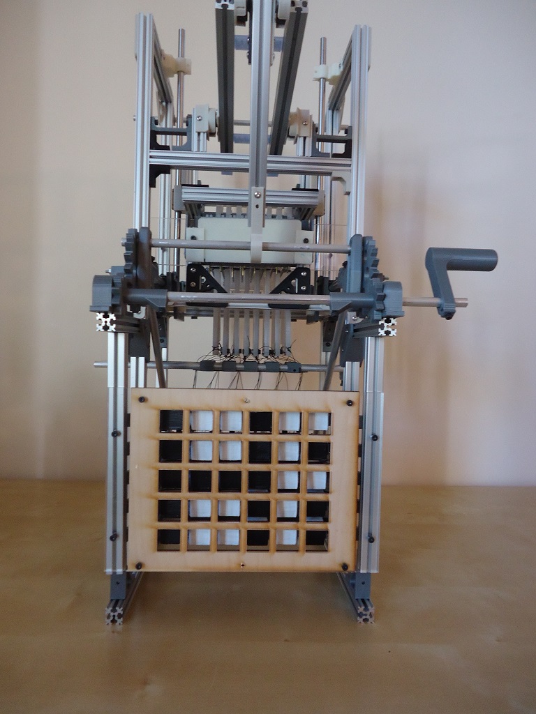
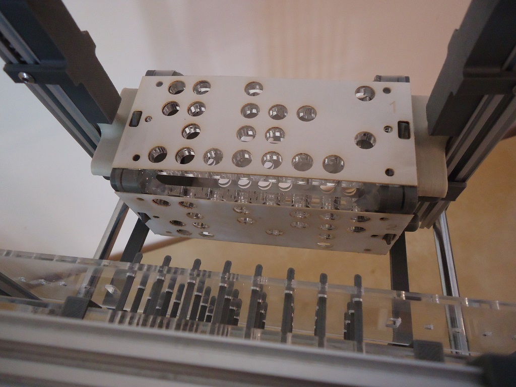
 The card reader is on top and the display on the bottom.
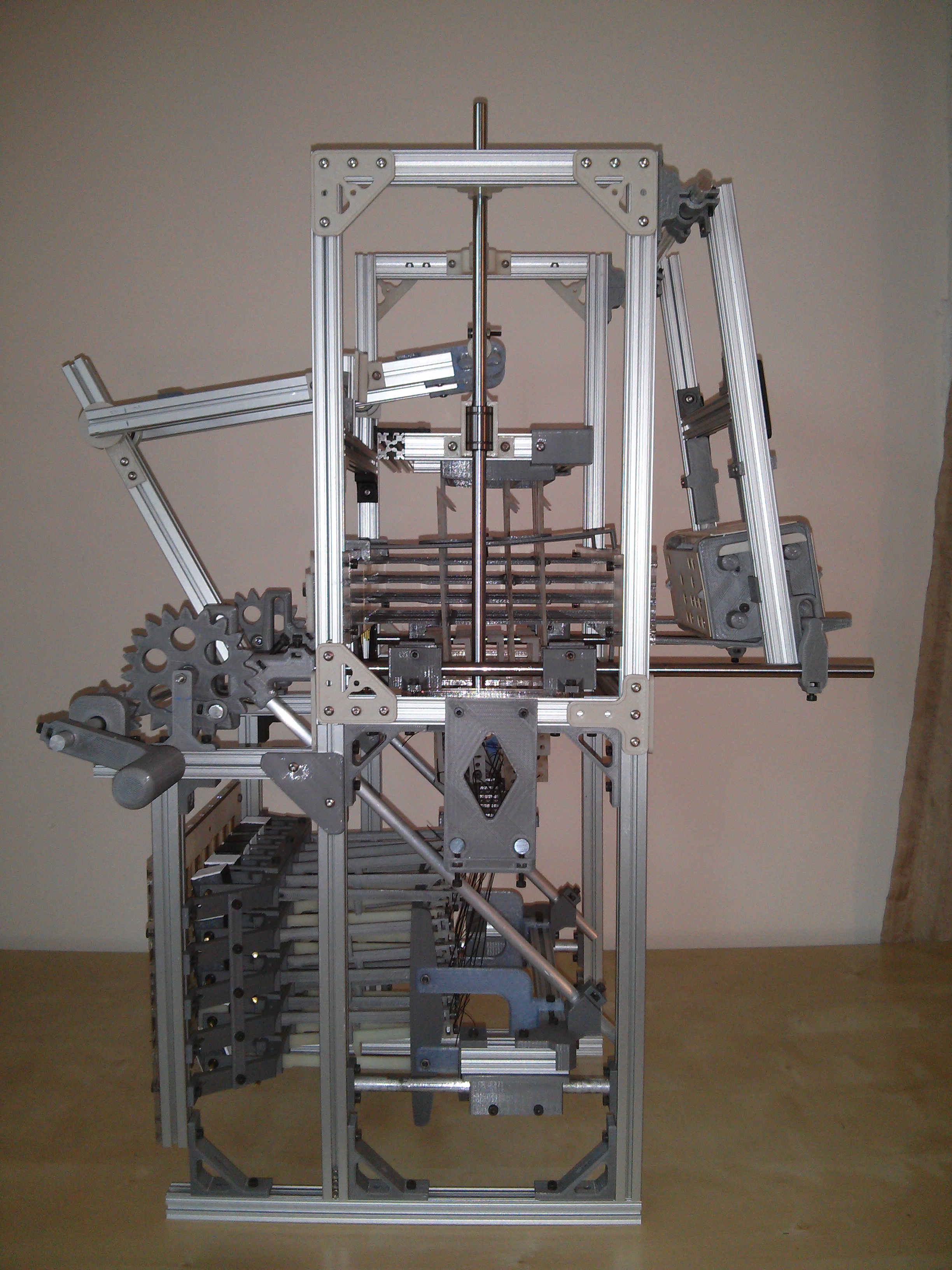
As a waypoint on my long road to figuring out how to build my own mechanical computer, I needed to figure out how to construct my own high-bit-count punch card reader. My previous machine, the Turbo Entabulator, had an incredibly simple (and yet somehow incredibly unreliable) 10-hook reader using a single row of hooks. “Real” power looms could handle 400-1200 hooks no problem. I wanted something large enough to be useful yet simple enough to build, and being a computer engineer, went with a nice round number like 32. The frame of the machine is mostly constructed out of 15mm x 15mm extruded T-slot aluminum (most of which was found when helping to clean up for last year’s NYCR Interactive Show!), which is great for building large-ish, rigid, lightweight structures. The T-slots are just big enough to capture an M3 nut, allowing you to easily bolt things to it and adjust them later.
The card reader itself is a single-acting, single-cylinder Jacquard machine with 4 rows of 8 hooks. A central drive-shaft (with the handle attached) provides power and timing for the whole machine (including the display). While in previous projects I’ve tried to be a purist about my construction methods (relying almost solely on 3D printing, for instance), this project was too complex to allow tying one arm behind my back like that, and uses the full extent of my terrible mechanical engineering and fabrication skills. The design itself is almost identical to the plans found in my now-favorite book “The Mechanism of Weaving.”
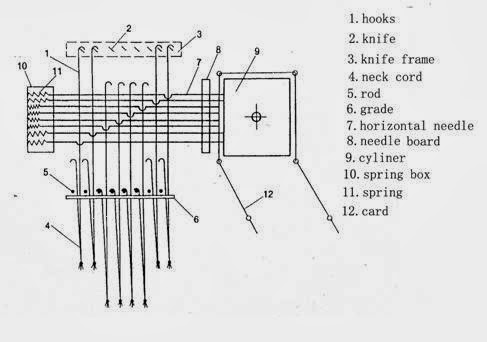 A simple card-reader design
One might be tempted to think “With all of these wonderful modern materials and computer-controlled tools, surely this design can be improved upon,” but they would be roundly mocked by their Victorian counterparts for their naive hubris. Almost any innovation I attempted resulted in abject failure, and I wound up just returning to the designs in the book. A big improvement over the design used in the Turbo Entabulator is that the in-out motion of the card cylinder is no longer driven indirectly from the up-down motion of the griff. The cylinder and the griff are both independently driven and timed from a rotating offset shaft (using a lever for the griff and a scotch-yoke mechanism for the cylinder). This both allows the relative motion to be adjusted much more easily and significantly reduces accumulated slop in the mechanisms. The offset shaft rotates with a 25mm radius, providing up to 50mm of throw for lifting the hooks and moving the cylinder. For linear motion, a combination of 8mm aluminum and steel rods were used in conjunction with linear bearings. Set-screws are used to attach things to the rods, although only the main drive shaft was actually filed down into a proper D-shape to provide a flat portion for the set-screw to push against.
 The artisanally-filed main drive shaft
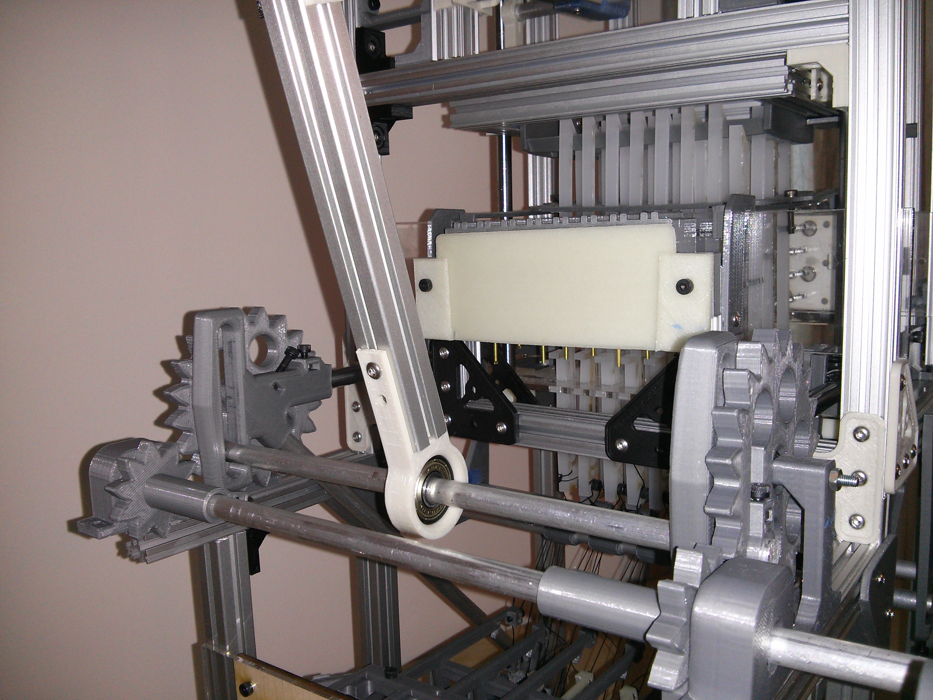
This design also differs from that of the Turbo Entabulator in that the cylinder now swings outward from a hinge at the top of the frame. I think this design may require less force than a purely linear movement of the card cylinder, at the expense of slightly trickier alignment, but I didn’t notice much difference between the schemes in practice.
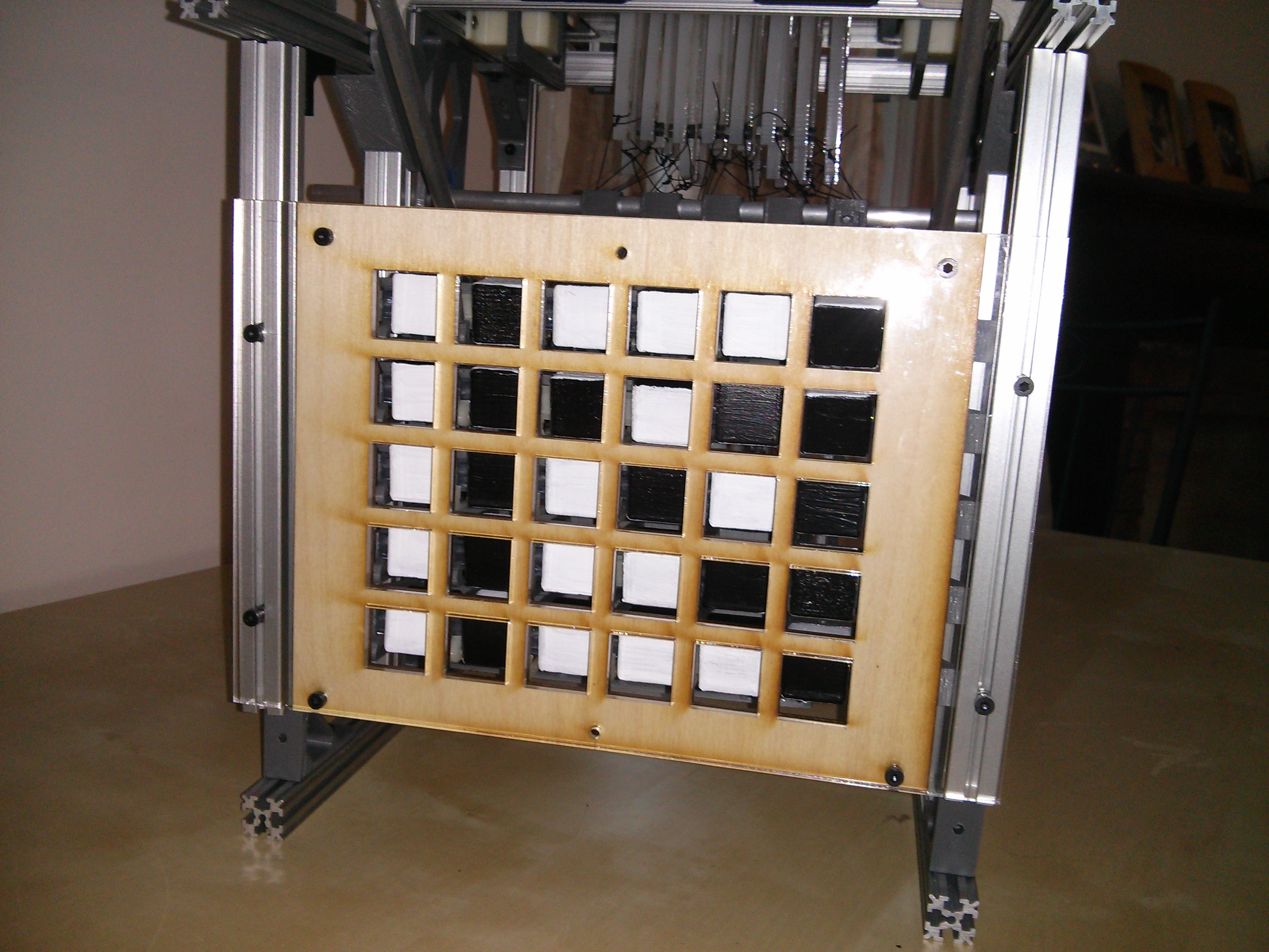
The Display
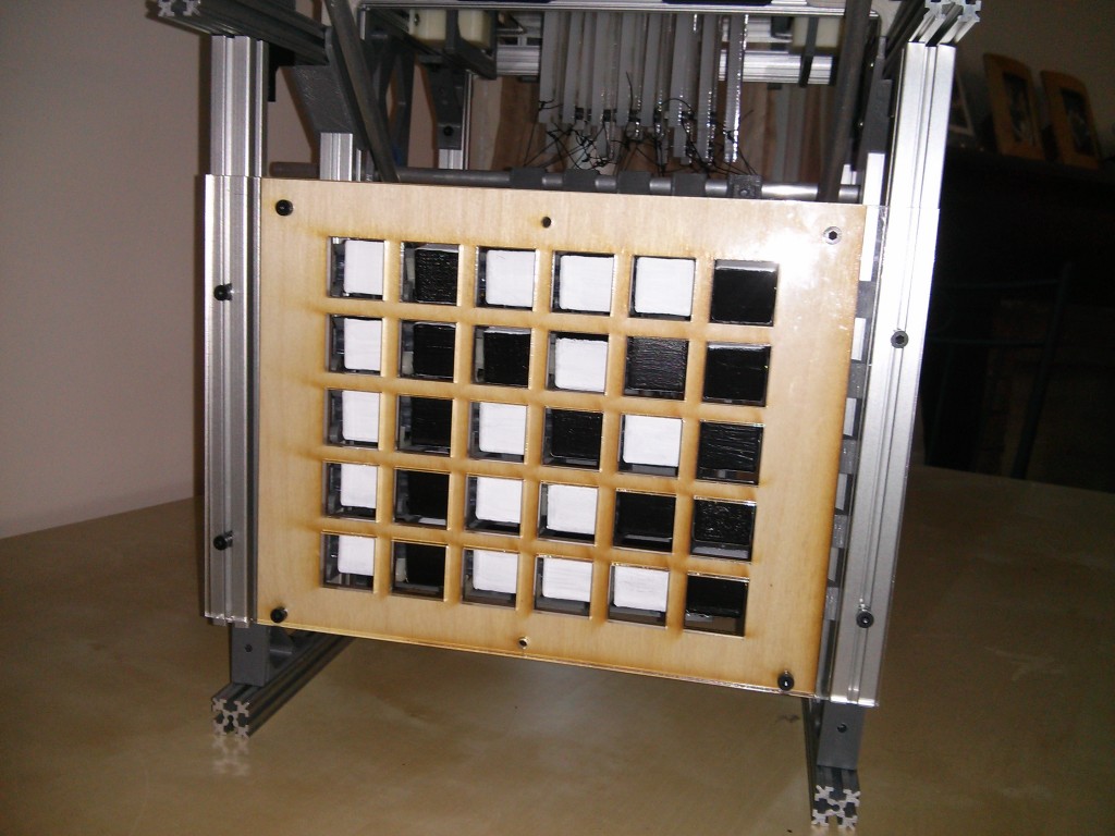 The world's lowest-resolution display
I’ve been toying around with the idea of building a mechanical display ever since I read The Difference Engine. If you know anything about power looms, it makes you realize that the kinotropes in the book could really have existed. People regularly built looms with thousands of hooks and card chains with 10s of thousands of cards, and they ran fast enough to read 3-4 cards a second, all in the name of making rugs at slightly lower prices! The book discusses kinotropes in somewhat vague terms, but it’s clear that they’re meant to be steampunk versions of our modern bit-mapped displays. They even have charming imperfections, like ‘kino-bits’ getting stuck (something my device, unfortunately, faithfully implements).
When it comes to actually building something, simpler is always better, so I went for a ‘minimum viable product’ approach. My punch card reader would let me control up to 32 control signals, and I knew my device wouldn’t be fast, so I wanted to make sure that 1 card == 1 frame of the animation. An ‘easy’ way to implement this might be to have 2 signals per ‘bit’ – one for white and one for black. This is basically how my Turbo Entabulator works, with 1 bit to increment and 1 to decrement each counter. It is also the approach taken by this extremely awesome LEGO-based mechanical display I saw a few weeks ago! While easy, though, it is wasteful, as that would leave me only able to control 16 pixels directly (or have some kind of indrect means of addressing smaller banks of pixels, but I had already ruled that out for speed reasons). An alternative design had occurred to me whereby I could ‘reset’ all of the pixels to black every cycle, and then selectively set the ones I wanted back to white. That would let me control up to 32 pixels, but there would be an annoying ‘flicker’ on every transition (much like a modern E-Ink display, actually). The flickering could be minimized mechanically by adjusting the timing to speed up as it reset and then have an extended dwell-time once the pixel was set, but it was still an annoying feature. I finally came up with a scheme that gave me both 1-signal-per-bit control and avoided the flickering effect, albeit at the expense of some ‘programming’ headaches.
Each pixel is implemented as a cube, with alternating faces painted black and white. By rotating the pixel 90 degrees it toggle from black-to-white or vice versa. This design could actually be extended to use color by painting the faces with different colors, and sequencing through them as necessary (with multiple cards needed to generate each ‘frame’, depending on the hamming distance between frames). Since the pixels are made using a 3D printer, a little 4-tooth ratchet wheel is printed onto one side of the cube, and a hole for an axle runs all the way through it so that the pixels can be assembled in rows. A thin ratchet arm mounted next to each pixel can toggle the pixel state if it is pulled backwards, and a flat-spring holdes the pixel in place as the ratchet arm returns to its resting position. From a minimum-viable-product perspective, being able to display text makes for a nice demo, so a 6×5 grid was chosen which plays nicely with my 32-bit punch cards (leaving 2 spare control signals in case I feel like getting fancy).
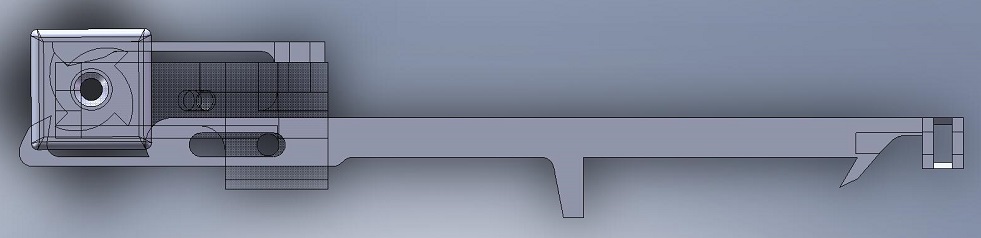 The pixel and ratchet mechanism
An important feature of this design is that the hooks of the punch card reader do not drive the ratchet arms directly. The hooks are happiest when applying a fairly delicate force (a useful analogy is trying to control a motor with a microcontroller – you don’t use the I/O pins directly!). When each ratchet arm is in its resting position, it is able to pivot slightly around an axle. The ratchet arm has a ‘hook’ built into the back of it, and another powerful griff mechanism driven directly by the main drive-shaft (like the one that lifts the hooks on the card reader) can catch this hook and pull it backwards. A nylon cord attaches each hook to the back of each ratchet arm, such that when the hook on the reader gets lifted upwards, it lifts the back of the ratchet arm safely out of the way of the ‘knives’ of the horizontal griff (ultimately causing the pixel to retain its current state).
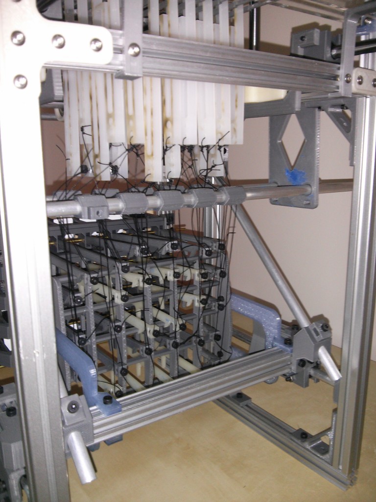 The scary web that connects the reader and the display
To minimize the force on the horizontal griff required to actuate up to 30 ratchet arms simultaneously, the ratchet arms do not have a rubber-band or spring to return them to their resting position. As the griff moves forward again after toggling the pixels to the next frame, the knives run into another protrusion extending from the ratchet arms, and they are safely pushed back into their resting position. This is probably the largest weakness of the design, as the ratchet arms occasionally get shaken slightly backwards by the movement of the rest of the machine (especially at higher speeds), causing the ratchet arm to miss the tooth of the wheel on the pixel, and thus causing that pixel to have the ‘wrong’ value until the ratchet slips again. Some very weak springs would probably improve the reliability of the machine immensely, but for now the trade-off was worth it as it allowed the griff to work reliably without flexing to a scary extent when actuating too many pixels.
If you’re feeling adventurous, download the files and make your own!
The Cards
 The card reader in action!
The punch cards control which hooks are lifted by the card reader’s griff as it moves upwards (a hole in the card means that the corresponding hook gets lifted). That hook is in turn tied to a ratchet associated with a pixel somewhere in the display. If the hook is lifted, the end of the ratchet is also lifted, and it is not pulled backwards by the horizontal griff that drives the display. If the hook remains down, the ratchet mechanism is pulled backwards, and the pixel is rotated 90 degrees, toggling the color of the pixel from white-to-black or vice versa. To recap, no hole means that pixel gets toggled.
Since the display uses a 6×5 pixel array, but the card reader is designed around an 8×4 array, some remapping needed to be done. The middle 6 pixels of the 4 card rows corresponds to the upper 4 rows of the display. The last row of the display is driven by the lowest 3 holes on the edges of each card, and the upper corner holes are just unused.
You can ‘program’ the display by setting the machine into a known starting state, and then figuring out which pixels need to be toggled to progress from frame to frame in the animation sequence. For the simple example that I used to test the machine, I wanted the machine to flash the letters ‘N Y C R’ in a loop (although I’d been working on this machine for a year or so, I hurried up and finished it for the 2015 NYCResistor Interactive Show). I haven’t had time to master creating long chains of punch cards yet, so my program uses just 4 cards that are taped around the cylinder so they loop indefinitely. Since the cards don’t ‘know’ about the current state of the display, I can play a fun trick while still only using 4 cards and have the display alternate from black-text-on-white-background to white-text-on-black-background on every iteration of the loop. This sort of scheme is known as a ‘card-saving technique’ in loom-land, although today we would probably call it a clever hack =)
I generated the card patterns by hand by drawing out the 4 frame transitions I wanted on 6×5 grids, and XORing the two frames together to make a 6×5 grid of pixels that need to toggle. I then mapped that to the 8×4 card pattern, drew up the cards in autocad and then lasercut them out of card stock. Eventually I would like to have a program that would just take in a series of bitmaps and automagically generate the card set in *.svg format for laser cutting, but I haven’t had time yet. Besides, the very labor intensive nature of programming it feels truer to its origins =)
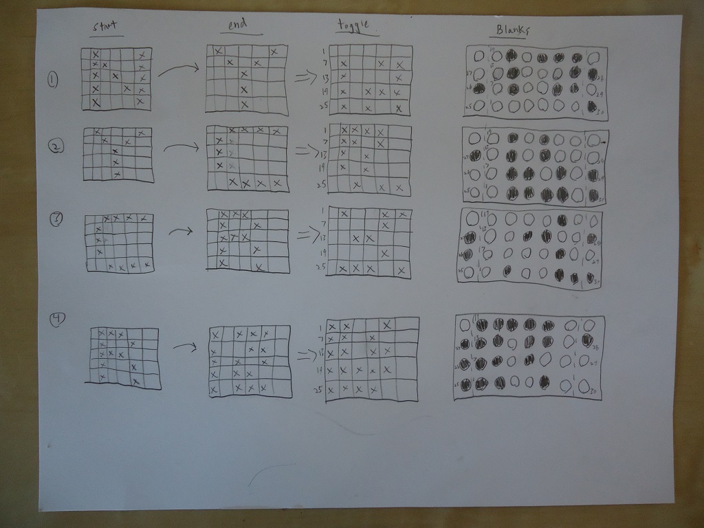 The worksheet used to 'compile' the "N Y C R" program
Steampunk Demoscene Time!
The aformentioned program flashing “N Y C R” and then inverting the display is shown below. Consider the gauntlet thrown, demosceners!
It is surprisingly hard to make your brain switch from reading black-on-white to white-on-black! For the more mechanically-inclined, here is a side-view of the machine in action, with all of the interacting mechanisms visible:
Future Work
The display was primarily chosen as a test vehicle for both the high-bit-count card reader and the double-griff control scheme, as both are requisites for designing a fancier mechanical computer some day. Also, I wanted to own my own Kinotrope because, you know, reasons. Happily, the display turned out to be really cool in its own right. I would like to do a bit of tuning to make the display more reliable, but it mainly needs work on the software front due to my ‘simplify the hardware and rely on magic software’ approach (it’s like the Itanium of mechanical displays!). For text-mode, it would be neat to make a program that takes in a line of text, and then spits out the punch cards necessary to make that text scroll across the screen in an SVG-format with a layout amenable to using with NYCResistor’s giant laser cutter. It would also be cool to do something similar with an arbitrary animation. It’s my firm belief that you could make some pretty rad Demos with this thing given enough time and patience. If any Internet Strangers feel like writing either of the aforementioned programs, feel free to go ahead and send them my way!